
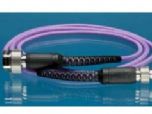
Gore PHASEFLEX Test Cable Assemblies Description:
GORE ® PHASEFLEX ® Microwave / RF test cable assemblies for production testing with a special design, can reduce the wireless infrastructure market, the total test cost of production test environment. Design of such components can withstand the frequent twisting, bending and vibration occurs frequently in test and production workshop environment.
Stable performance of these components can be tested to ensure the accuracy and repeatability, reducing the risk of testing errors, and reduced troubleshooting and system calibration and wasted man-hours. Enhanced durability and flexibility make these cables have a longer life, thereby reducing demand for cable replacement and test cost savings. Further, without using the torque wrench to test the components, and thus increases the output of the production line.
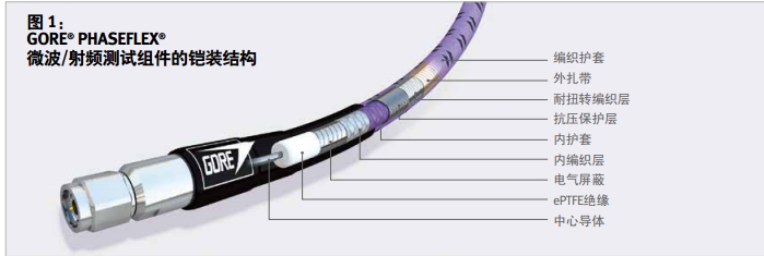
Special structural design of such components has the following key features:
Flexible, rugged casing stress release
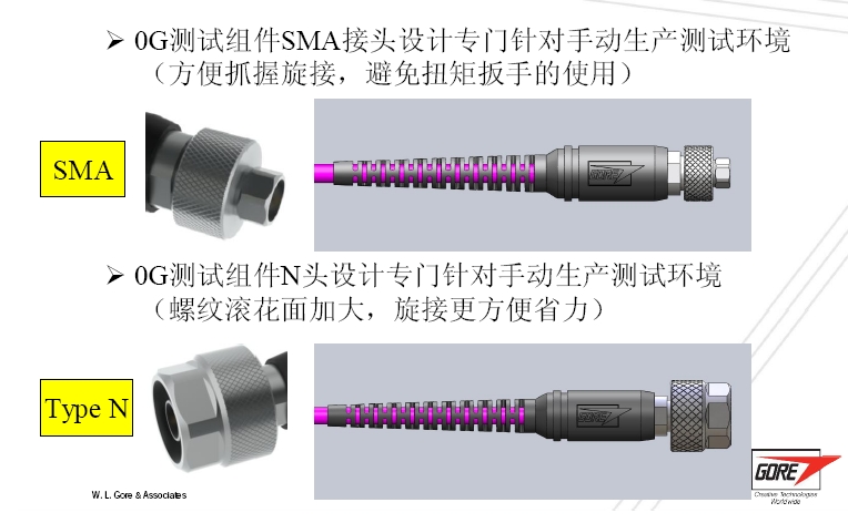
Easy to grip, fast spin-fit connector; without the use of a torque wrenc
Cable structure durable, highly flexible, small diameter of
| Gore Cable Type | 0G | |
|---|---|---|
| The maximum frequency (GHz) | 6 | 18 |
| Typical VSWR (VSWR) | 1.08:1 | 1.27:1 |
| Typical insertion loss (dB) | 1.2 | 2.19 |
| Impedance (nominal)(Ohms) | 50 | |
| Typical phase stability (degrees)2 | ± 0.5 | ± 2.0 |
| Typical amplitude stability (dB)2 | < ± 0.05 | |
| Dielectric constant (nominal) | 1.4 | |
| Propagation velocity (nominal)(%) | 85 | |
| Shielding Effectiveness(dB - 18 GHz)3 | > 100 | |
| Delay (nominal)ns/cm (ns/in) | 0.04 (0.103) | |
| Center conductor | Solid |
| Cable diameter mm (in) | 5.3 (0.210) |
| Nominal Weight g/m (oz/ft) | 65.0 (0.70) |
| minimum bend radius mm (in) | 25.4 (1.00) |
| Typical Flexlife4 | 100,000 |
| Temperature Range (°C) | -55 - 125 |
| Withstanding pressure kgf/cm (lbf/in) | 33.5 (187) |
| Connector tensile N (lbf) | >445 (>100) |
1 Table based on the length of the electrical parameters 1 m (39.4 in), frequency of 6 GHz and 18 GHz components.
3 Around the radius of the cable 57 mm (2.25 in) for the value of the winding mandrel test.
3 Reference test specification MIL-STD-1344, Test Method 3008.
4 In the case of twice the minimum bend radius bend ± 90 ˚, bending test components throughout the lifetime of reliable performance requirements are maintained.
| Model | Cable Type | Connector A | Connector B |
Length in/(m) |
|---|---|---|---|---|
| 0G0S10S1039.4 | 0G | SMA male | SMA male | 39.4/(1.00) |
| 0G0N10S1039.4 | 0G | Precision N-type male | SMA male | 39.4/(1.00) |
| 0G0N10N1039.4 | 0G | Precision N-type male | Precision N-type male | 39.4/(1.00) |
| 0G0S10S1059.1 | 0G | SMA male | SMA male | 59.1/(1.50) |
| 0G0N10S1059.1 | 0G | Precision N-type male | SMA male | 59.1/(1.50) |
| 0G0N10N1059.1 | 0G | Precision N-type male | Precision N-type male | 59.1/(1.50) |
Next:gore RF and microwave test cable assemblies
Previous:Nothing